
Using an Ultrasonic Sensor to Measure Distance with Arduino
Using an Ultrasonic sensor is one of the easiest ways to measure distance with an Arduino. The most popular, commonly available, and best supported sensor is the HC-SR04. You can find these for purchase all over the internet along with wiring schematics, tutorials, and videos.
Let’s start by figuring out the parts and materials we will need, then learn how to wire the HC-SR04 to the Arduino and finally write some code to control it and read back the distance measurement data.
Step 1: Gather Materials:
HC-SR04 Ultrasonic Sensor
Arduino UNO
Breadboard
Breadboard jumper wires
Computer with Arduino IDE installed
I will be using an Arduino UNO in this tutorial, however, other Arduino boards such as the Nano will work. The breadboard makes setting this project up much quicker and easier. It also lets you re-use the components after finishing this project. If you are building this as a permanent solution feel free to solder it all together! We will need 4x Male to Male jumper wires to connect the pins on the HC-SR04 to the Arduino.
Step 2: Wire Everything Together
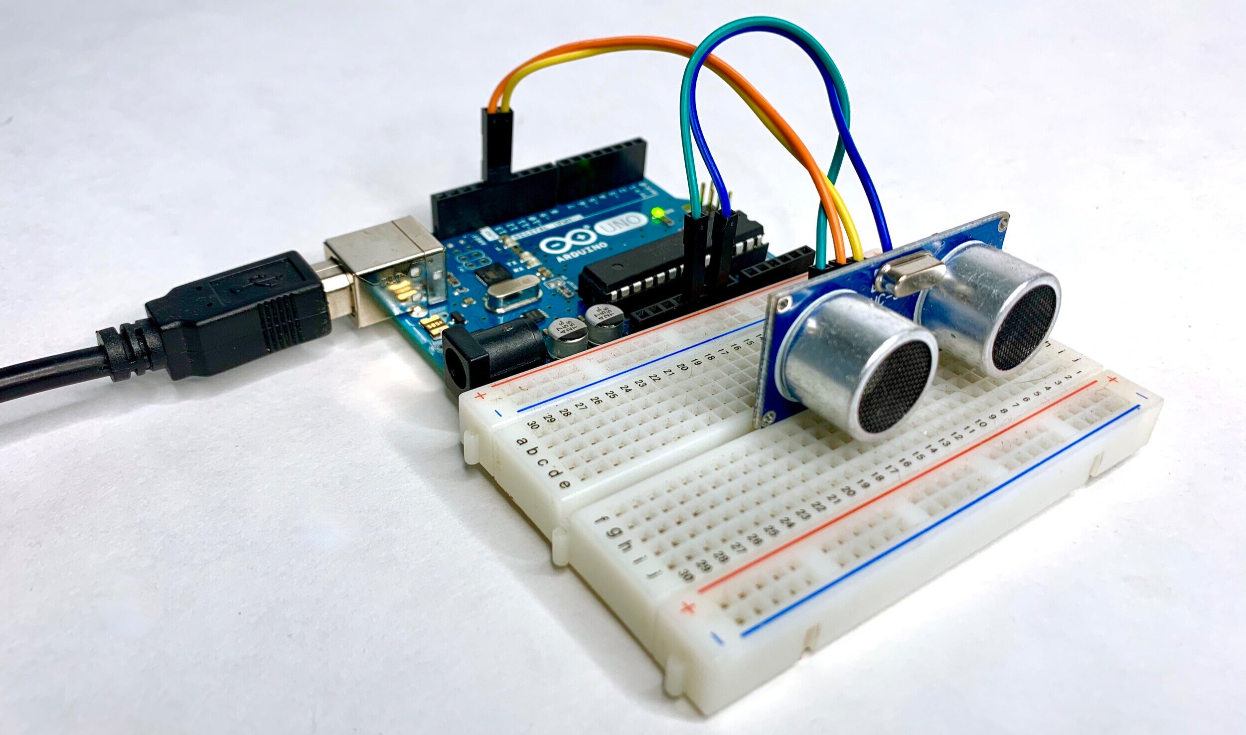
Let’s start by putting the HC-SR04 into the breadboard. You want to put it in the breadboard so that each pin is in its own row, or component rail. See Figure 1 below as a reference.
Now lets connect the wires:
Connect the Ground Pin (Gnd) from the HC-SR04 to a Gnd pin on the Arduino board
Connect the Voltage In pin (Vcc) from the HC-SR04 to the 5v out on the Arduino
Connect the Trig pin from the HC-SR04 to pin 13 on the Arduino
Connect the Echo pin from the HC-SR04 to pin 12 on the Arduino

Figure 1
Step 3: Write and Upload the Code
First make sure you have the Arduino IDE installed: https://www.arduino.cc/en/software
Now that everything is wired and ready, all we need to do is write the code to control the HC-SR04. We will also set up serial monitoring so we can read back the data from the sensor to see what’s going on. Go ahead and follow the code snippet below:
const int echoPin = 12; //Define the Echo Pin
const int trigPin = 13; //Define the Trig Pin

long duration;          //Define a variable to hold the ping duration
int distance;           //Define a variable to hold the distance value
long randomNumber;      //Define a variable to hold a random value

void setup() {

  pinMode(echoPin, INPUT);    //Set Echo Pin as INPUT
  pinMode(trigPin, OUTPUT);   //Set Trig Pin as OUTPUT

  duration = 0;               //Initilize duration as 0
  distance = 0;               //Initilize distance as 0

  Serial.begin(9600);

}

void loop() {

  digitalWrite(trigPin, LOW);          //Clears the Trig Pin
  delayMicroseconds(2);                //Wait for clear
  digitalWrite(trigPin, HIGH);         //Set the Trig Pin to HIGH
  delayMicroseconds(10);               //Leave on HIGH for 10 μs
  digitalWrite(trigPin, LOW);          //End Ping by setting trig pin to LOW
  duration = pulseIn(echoPin, HIGH);   //Reads the Echo Pin and returns the duration of sound wave travel
  distance = duration * 0.034 / 2;     //Calculate the speed of the sound wave and divide by 2 (out and back)

  Serial.print("Distance: ");
  Serial.println(distance);

}
Alright! Now let’s save and upload the code to the board. Make sure your Arduino board is plugged into your computer with the USB cable.
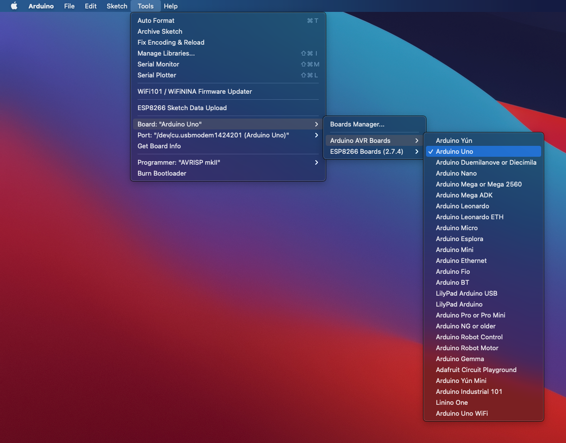
Go to Tools > Board: > Arduino AVR Boards > Arduino Uno
2. Go to Tools > Port: > select the correct port for your Arduino… It will usually have be the usbmodem port, but this will vary between operating systems.

3. If you haven’t already, go ahead and save your Arduino sketch. You can do this from the file menu, or by pressing the Verify button. If you haven’t already saved your file, clicking the Verify button will prompt you to do so. It will then proceed to “verify” your code and check it for any errors.

4. Click the upload button to upload the code to your Arduino board

Step 4: Power Up and Test!
Now that everything is good to go, keep your Arduino plugged into your computer so that we can monitor the serial data and keep it powered.
When you upload the code to your Arduino, the board automatically resets and begins executing your code. We can now open the Serial Monitor to monitor the serial data from the HC-SR04 sensor.

You can see that as you move an object closer and further from the sensor the distance value changes! You can use this for all sorts of applications like object avoidance, triggering events, light up a warning LED when an object is too close or too far, and an infinite number of other possibilities!