
Powering a Raspberry Pi with a Battery
So you just got your new Raspberry Pi and you are excited to hook it up to your newly built robot. Your Raspberry Pi will be the brains of your robot as it navigates through the world collecting data from multiple sensors and autonomously navigating using computer vision. You write all of your code, mount the Pi to your robot, and plug it in. Wait… the power adapter is only three feet long?!?
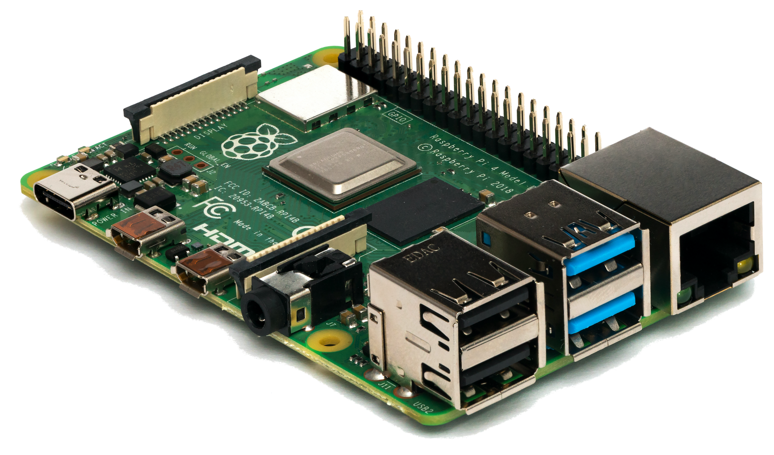
What is a Raspberry Pi?
Raspberry Pi’s are great little compact computers about the size of a deck of cards. You can put it in a little box, hook up a monitor, keyboard, and mouse and have a desktop computer powerful enough to do day to day things. They also have a unique feature which I will refer to as the GPIO pins. These GPIO pins allow you to hook up different accessories like sensors, motors, other boards, and interact with them through interfaces or scripts on your Raspberry Pi. Sounds cool right? A fully functioning computer the size of a deck of card that I can strap to my robot? Well yes! But the Raspberry Pi isn’t exactly compatible with your good old AA batteries, or that 12V Lipo you have laying around… right out of the box. However, we are engineers right? We can make anything work. Well of course! Let’s look at some different ways we can cut the cable for our Raspberry Pi!
What are the requirements?
Raspberry Pi’s are very picky and want exactly 5.1V (+/- 5% or so). The current will vary based on model, and how hard you are making your Pi work. So we need to find a way to supply a steady 4.9V - 5.3V to the Pi.
What are some options?
Here are three ways you can regulate the input voltage for your Raspberry Pi. I have listed them in order of my favorites top to bottom, but your requirements may be different based on your specific project. Read about each to find out if one of these options will work for your project!
Option 1: Switching Voltage Regulator (Good Option - Most efficient)
A Switching Voltage Regulator like the LM2596 will allow you to use an input voltage between 3V - 40V and regulate it to output anything from 1.5V to 35V. Once your power supply has been attached, you can adjust the screw on the potentiometer to set your desired output voltage. In the case of the Raspberry Pi, the output would be 5.1V. The biggest advantage of using a Switching Voltage Regulator is that it is going to be the most energy efficient. Basically, the voltage regulator switches on and off thousands of times per second (in the case of the LM2956 - 150,000 times per second - 150kHz). Each time it switches on it builds up energy in the internal capacitors to the desired voltage, then shuts off consumption from the power supply. By doing this tens of thousands of times per second, it maintains a constant voltage while consuming less energy.
Cons
Most expensive (but still cheap)
Can have higher electronic noise than a Linear Voltage Regulator
Larger footprint
Pros
Really easy to use
Fixed output once set
Most energy efficient
Low heat dissipation


LM2596 Wiring Schematic
Option 2: Linear Voltage Regulator (Good Option - Very easy)
A Linear Voltage Regulator offers the same functionality as a switching voltage regulator, but in a smaller and cheaper package. In order to be smaller and cheaper, the linear voltage regulator sacrifices efficiency. Instead of switching on and off, the linear regulator simply bleeds off excess energy as heat. If using a battery (as is the point of this article), you will find that the linear regulator fluctuates the least as the battery voltage drops. It will maintain a constant output. We have been successful using the L7805 in various projects. Be aware, at higher input voltages the heat sink the little chip wears as a hat can get very hot!
Cons
Not so energy efficient
Can generate excessive heat
Pros
Cheap and small
Easy to integrate into your project
Maintains a constant output even as input voltage nears the output


L7805 Wiring Schematic
Option 3: DIY Voltage Divider (Not recommended)
While this is not recommended for regulating the power supply for your Raspberry Pi, I thought I would mention it. Building a voltage divider is one of the basic principles of electronics and is based on the voltage division rule.
And the circuit is built as follows:

You need to keep in mind the power requirements of your project. If you are going to be running very high loads, you want to make sure you are using resistors that are made to handle those loads. If your resistors are not sufficient, you run the risk of burning up your project!
Cons
Input voltage must be constant (Vout will drop as Vin drops)
Complexity of components grows with the complexity of your project.
LOTS of heat dissipation, could burn
Pros
Cheap and simple